Packet Tracer
Building a Fully Redundant Multilayer Network in Cisco Packet Tracer
Overview :
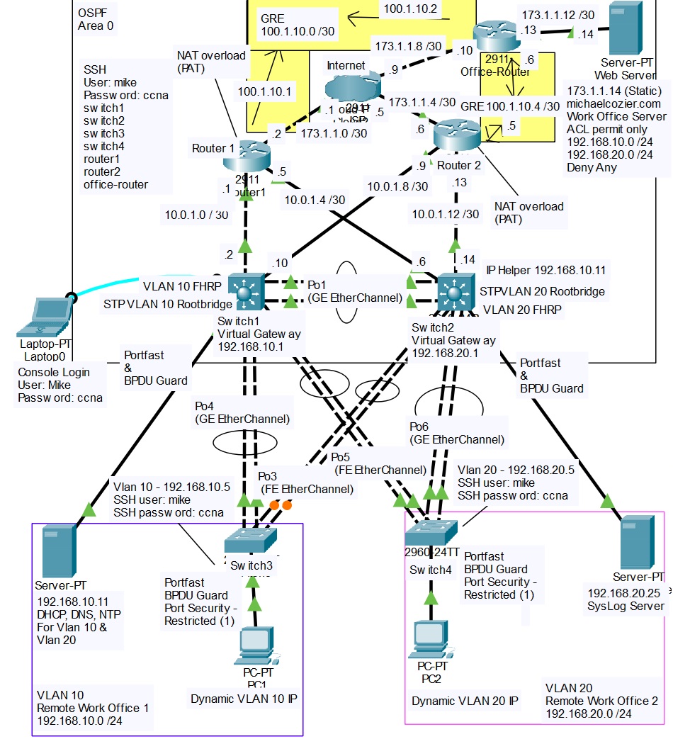
In this project, I designed and implemented a high-availability enterprise network in Cisco Packet Tracer. The environment includes redundancy at every layer, dynamic routing, VLAN segmentation, First Hop Redundancy Protocols (FHRP), Access Control Lists (ACLs), DNS, GRE tunneling, centralized Syslog monitoring, and secure SSH-based management. The design mirrors a real-world enterprise multilayer architecture and demonstrates advanced switching, routing, and security concepts developed during my CCNA preparation.Network Topology and Features
- Two Cisco 3560 multilayer switches acting as the core/distribution layer
- Two Cisco 2960 switches at the access layer
- Two Cisco 2911 routers providing redundant WAN connectivity
- Office router simulating a remote site
- Redundant GRE tunnels between sites
- Internal DHCP and DNS server
- Centralized Syslog server
- External ISP cloud for Internet simulation
VLANs and Subnets VLAN 10 Subnet: 192.168.10.0/24 Purpose: Server and PC1 segment Default Gateway (HSRP): 192.168.10.1 STP Root and HSRP Active Device: MSW1 VLAN 20 Subnet: 192.168.20.0/24 Purpose: User and PC2 segment Default Gateway (HSRP): 192.168.20.1 STP Root and HSRP Active Device: MSW2
DHCP Relay Configuration Centralized IP address management is enabled using DHCP relay on the SVIs: interface vlan 20 ip helper-address 192.168.10.11 This allows all VLANs to receive DHCP services from a single server located in the server VLAN.
Dynamic Routing and GRE Tunneling OSPF Configuration • All VLANs, server networks, and management subnets are advertised in OSPF Area 0 • Both multilayer switches form adjacencies with both routers • Equal-cost multi-path (ECMP) routing provides load balancing and automatic failover GRE Tunnels To maintain site-to-site connectivity, redundant GRE tunnels were deployed: Tunnel 10 Router1 to Office Router (Primary) Tunnel 20 Router2 to Office Router (Backup) Both tunnels run OSPF to ensure dynamic routing and seamless failover. Example GRE configuration: interface Tunnel0 ip address 100.1.10.1 255.255.255.252 tunnel source gigabitEthernet0/0 tunnel destination 173.1.1.10 tunnel mode gre ip
Layer 2 Redundancy and FHRP Spanning Tree Protocol (Rapid-PVST+) • MSW1 is the STP root bridge for VLAN 10 • MSW2 is the STP root bridge for VLAN 20 This ensures predictable forwarding paths and fast convergence. HSRP Gateway Redundancy • VLAN 10 uses virtual gateway 192.168.10.1 • VLAN 20 uses virtual gateway 192.168.20.1 HSRP active routers are aligned with STP root placement to avoid suboptimal traffic paths.
EtherChannel Configuration Multiple physical links are bundled between access and distribution layers using EtherChannel: interface range g0/1 - 2 channel-group 1 mode active Benefits include increased bandwidth, link redundancy, and simplified STP topology.
DNS Integration The internal DNS server at 192.168.10.11 resolves both internal and external hostnames. Example DNS record: michaelcozier.com resolves to 173.1.1.14 Verification commands: ping michaelcozier.com nslookup michaelcozier.com
Access Control Lists (ACLs) Standard ACLs are used to restrict traffic between VLANs and protect the server network: access-list 10 permit 192.168.10.0 0.0.0.255 access-list 10 permit 192.168.20.0 0.0.0.255 access-list 10 deny any This ensures only authorized internal traffic can access server resources while blocking unwanted access attempts.
Secure Management and SSH Configuration Console and Local Access line console 0 password ccna login exec-timeout 5 0 logging synchronous SSH Remote Management hostname MSW1 ip domain-name michaelcozier.com crypto key generate rsa modulus 2048 ip ssh version 2 username mike privilege 15 secret ccna line vty 0 15 transport input ssh login local SSH access is encrypted and authenticated locally, allowing management using DNS hostnames instead of IP addresses. Test examples: ssh -l mike switch1 ssh -l mike router1
Centralized Syslog Integration A Syslog server located at 192.168.20.25 collects logs from all switches and routers. Configuration example: logging host 192.168.20.25 logging trap informational service timestamps log datetime msec service sequence-numbers This provides: • Visibility into OSPF and HSRP state changes • STP root changes and link status monitoring • Audit trails for device login attempts • Faster troubleshooting during failover events
Testing and Validation • DHCP successfully assigned IP addresses, gateways, and DNS • DNS resolution worked across VLANs and through OSPF • ACLs enforced proper segmentation • HSRP failover occurred with minimal interruption • OSPF dynamically reconverged after link failures • GRE tunnels maintained external connectivity • EtherChannel links provided fault tolerance • Syslog captured events in real time • SSH access verified using DNS-based hostnames
Why This Design Works • End-to-end redundancy eliminates single points of failure • Centralized logging improves visibility and troubleshooting • STP and HSRP alignment optimizes traffic flow • Secure management protects control and data planes • Scalable architecture supports future VLANs, sites, and tunnels